DA-12050 Owner’s Manual
Download PDF Manual>>>
PDF Manual Library>>> | PDF Specifications Library>>> | PDF CAD Library>>>

SAFETY INSTRUCTIONS

Explanation of Graphical Symbols


1. Read Instructions – All the safety and operating instructions should be read before the appliance is operated.
2. Retain Instructions – The safety and operating instructions should be retained for future reference.
3. Heed Warnings – All warnings on the appliance and in the operating instructions should be adhered to.
4. Follow Instructions – All operating and other instructions should be followed.
5. Water and Moisture – The appliance should not be used near water – for example, near a bathtub, washbowl, kitchen sink, laundry tub, in a wet basement, or near a swimming pool, etc.
6. Carts and Stands – The appliance should be used only with a cart or stand that is recommended by the manufacturer.

7. Wall or Ceiling Mounting – The appliance should be mounted to a wall or ceiling only as recommended by the manufacturer.
8. Ventilation – The appliance should be situated so that its location or position does not interfere with its proper ventilation. For example, the appliance should not be situated on a bed, sofa, rug, or similar surface that may block the ventilation openings; or placed in a built-in installation, such as a bookcase or cabinet that may impede the flow of air through the ventilation openings.
APPLICABLE FOR USA, CANADA, OR WHERE APPROVED FOR
USAGE
CAUTION: TO PREVENT ELECTRIC SHOCK, MATCH WIDE BLADE
PLUG TO WIDE SLOT, INSERT FULLY.
ATTENTION: POUR EVITER LES CHOCS ELECTRIQUES, INTRODUIRE
LA LAME LA PLUS LARGE DE LA FICHE DANS LA BORNE
CORRESPONDANTE DE LA PRISE ET POUSSER JUSQU AU FOND.
9. Heat – The appliance should be situated away from heat sources such as radiators, stoves, or other appliances that produce heat.
10. Power Source – The appliance should be connected to a power supply only of the type described in the operating instructions or as marked on the appliance.
11. Power-Cord Protection – Power-supply cords should be routed so that they are not likely to be walked on or pinched by items placed upon or against them, paying particular attention to cords at plugs, convenience receptacles, and the point where they exit from the appliance.
12. Cleaning – The appliance should be cleaned only as recommended by the manufacturer.
13. Nonuse Periods – The power cord of the appliance should be unplugged from the outlet when left unused for a long period of time.
14. Object and Liquid Entry – Care should be taken so that objects do not fall into and liquids are not spilled into the inside of the appliance.
15. Damage Requiring Service – The appliance should be serviced by qualified service personnel when:
a. The power-supply cord or the plug has been damaged, or
b. Objects have fallen onto, or liquid has been spilled into the appliance; or
c. The appliance has been exposed to rain; or
d. The appliance does not appear to operate normally or exhibits a marked change in performance; or
e. The appliance has been dropped, or the cabinet damaged.
16. Servicing – The user should not attempt to service the appliance beyond those means described in the operating instructions. All other servicing should be referred to qualified service personnel.
17. Grounding or Polarization – The precautions that should be taken so that the grounding or polarization means of an appliance is not defeated.
FUNCTIONS
Level Controls – Allows any of the channels to be adjusted independently to raise or lower the output of each channel.
R R+L L Switch – When BUS input is selected, this switch is used to direct the channel to play the left signal from the input “L” or the right signal from the input “R”, or combined right and left signal from the input “R+L”.
BUS*LINE Switch – Allows each channel to play a variety of different inputs. Depending on the switch position the channel amplifies the signal connected to the BUS input and its own LINE input.
POWER MODE SELECTION
There are three ways to turn the amplifier on and off:
1. Manual – Use this selection when you wish to manually turn the amplifier on and off by using the front power button.
2. Trigger – Use this selection to turn on the amplifier when it receives voltage (3-24V A/C or D/C) from an external source and turns off once that voltage has stopped. The voltage source must be connected to the trigger-input jack on the back of the amplifier.
3. Audio Sense – The amplifier will automatically turn on when the amplifier’s main input receives an audio signal. At the moment that either the left or right input jacks receive a signal, the amplifier will automatically turn on. Once the signal stops, the amplifier automatically goes into standby mode.
BRIDGE MODE
To bridge two adjoining channels move the switch marked “BRIDGE” to the “ON” position. The output of the combined channels can then be used to power one speaker. Do not connect more than one speaker to the outputs of the bridged channel.
3-24V DC/AC Trigger in – 3-24V AC or DC input to trigger power up with voltage from another device, such as a receiver. The voltage source must be connected to the trigger-input jack on the back of the amplifier.
12V DC Control Out – The 12V output jack on the back of the amplifier can be used to turn on a variety of components equipped to be activated when they receive a 12V DC output.
Rated Power Output
50 Watts per channel at 8Ω
60 Watts per channel at 4Ω
Frequency Response:
±0.7dB, 20Hz to 20kHz, 8Ω
±1.5dB, 20Hz to 20kHz, 4Ω
Bridged Power Output:
120 Watts at 8Ω
Damping Factor:
>60
S/N Ratio:
(A-WTD) >102 dB
Total Harmonic Distortion:
<0.5% 20Hz to 20kHz
Input Sensitivity:
900mV for 8Ω rated output
Fuse Rating:
120V Version: T12A/250V
Input Impedance:
>22K Ω Bus
>10K Ω Line
FEATURES
1. 2U Rack Height
2. Bridgeable adjoining channels
3. Independent level control for each channel
4. Independent circuitry safety protection for each channel
5. Pass-through bus output allows daisy chaining of multiple amplifiers
6. 3-24v AC/DC remote power on trigger input
7. 12v control out remote power on trigger for other devices with voltage trigger
8. Includes rack ears
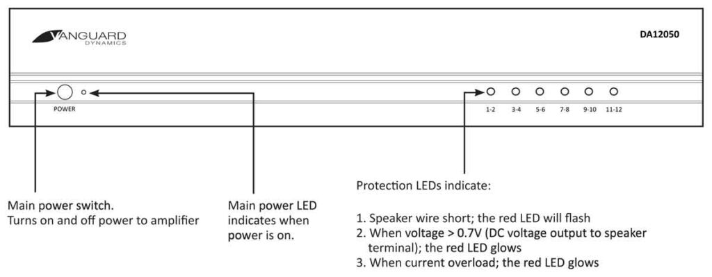
FRONT PANEL
REAR PANEL

LIMITED 5-YEAR WARRANTY
Vanguard Dynamics warrants to the original retail purchaser only that this Vanguard Dynamics product will be free from defects in materials and workmanship for a period of five years, provided the product was purchased from a Vanguard Dynamics Authorized Dealer. Defective products must be shipped, together with proof of purchase, prepaid and insured to the Vanguard Dynamics Authorized Dealer from whom they were purchased, or to the Vanguard Dynamics factory at the address listed on this installation instruction manual. Freight collect shipments will be refused. It is preferable to ship this product in the original shipping container to lessen the chance of transit damage. In any case, the risk or loss or damage in transit is to be borne by the purchaser.
If upon examination at the Factory or Vanguard Dynamics Authorized Dealer it is determined that the unit was defective in materials or workmanship at any time during this warranty period, Vanguard Dynamics or the Vanguard Dynamics Authorized Dealer will, at its option, repair or replace this product at no additional charge, except as set forth below. If this model is no longer available and can not be repaired effectively, Vanguard Dynamics, at its sole option may replace the unit with a current model of equal or greater value. In some cases where a new model is substituted, a modification to the mounting surface may be required. If mounting surface modification is required, Vanguard Dynamics assumes no responsibility or liability for such modification.
All replacement parts and products become the property of Vanguard Dynamics. Products replaced or repaired under this warranty will be returned to the original retail purchaser, within a reasonable time, with freight prepaid. This warranty does not include procedures, commercial use, voltage inputs in excess of the rated maximum of the unit, or service, repair or modification of the product which has not been authorized or approved by Vanguard Dynamics. This warranty also excludes normal cosmetic deterioration caused by environmental conditions.
This warranty will be void if the serial number on the product has been removed, tampered with or defaced. This warranty is in lieu of all other expressed warranties. If the product is defective in materials or workmanship as warranted above, the purchaser’s sole remedy shall be repair or replacement as provided above. In no event will Vanguard Dynamics be liable for any incidental or consequential damages arising out of the use or inability to use the product, even if Vanguard Dynamics or a Vanguard Dynamics Authorized Dealer has been advised of the possibility of such damages, or for any claim by any other party. Some states do not allow the exclusion or limitation of consequential damages, so the above limitation and exclusion may not apply. All implied warranties on the product are limited to the duration of this expressed warranty. Some states do not allow limitations on the length of an implied warranty. If the original retail purchaser resides in such a state, this limitation does not apply.